Potential Dividers
Summary
⇒ Potential dividers are simple, three-component circuits designed to control the potential difference in a circuit
⇒ They consist of a power supply (such as a cell); a fixed resistor; and a third resistive component, whose resistance can be fixed (fixed resistor) or variable (variable resistors, thermistors, light-dependent resistors, etc.)
⇒ All of these components are connected in series nd the emf of the power supply is shared across the two resistive components
⇒ The clue to how potential dividers work is in their name, potential dividers i.e. something that splits up potential difference - see the following example:
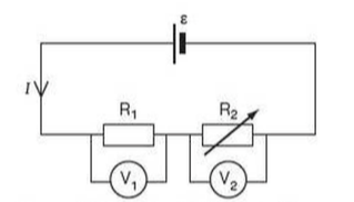
⇒ Generally we are trying to vary the potential difference V1 (across R1) by varying R2
⇒ Assuming that the cell has negligible internal resistance, then the total resistance of the circuit RT is given by: RT = R1 + R2
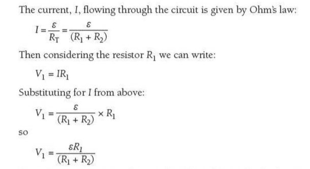
⇒ From this equation it can be seen that if ε and R1 are fixed, then V1 only depends on R2. In fact, as R2 increaes, V1 decreases, and vice versa
Potential Dividers as Sensors
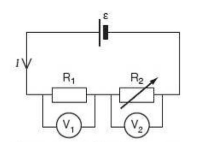
⇒ Another use of the potential divider is in sensor circuits
- If the variable resistor, R2, in the potential divider circuit below is replaced with a component whose resistance varies with an external physical variable such as temperature or light intensity, then the potential difference across the fixed resistor, R1, will also vary with the external physical variable
⇒ The voltemeter connected across R1 can then be calibrated in terms of the value of the external physical variable
- The circuit can then be made to act as an electronic thermometer or an electronic light sensor
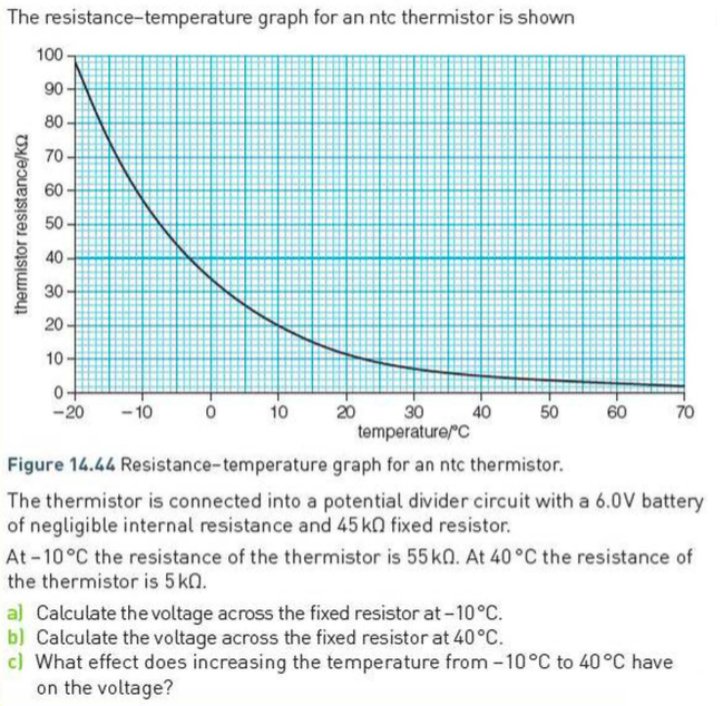
⇒ With an electronic thermometer, a thermistor is connected in place of R2
- Most thermistors are ntc (negative temperature coefficient) thermistors
- This means that as the temperature increases, their resisstance decreases, as shown below:
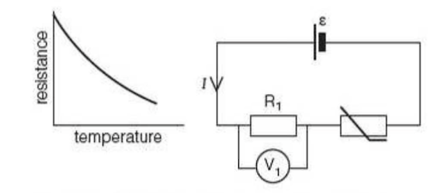
⇒ The effect on the potential difference across the fixed resistor R1 is that as the temperature increases, so the resistance of the thermistor, R2, drops and V1 rises
- Thus increasing temperature produces increasing potential difference
- If the voltmeter is connected acrosss the thermistor, the opposite will happen: increasing the temperature will produce a decrease in potential difference
Example
Light Dependent Resistors
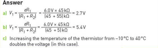
⇒ A similar effect involves the use of a light-dependent resistor (LDR)
- These are components that change their resistance with light intensity, which makes them incredibly useful as light sensors
- LDRs are made of semi-conducting materials; as the light shines on the material electrons are freed from the structure and can flow through it, reducing the resistance of the LDR
⇒ In the dark, LDRs can have a very high resistance, of the order of megaohms, and yet in the light their resistance can drop as low as a few hundred ohms
⇒ If an LDR is connected into a potential divider in place of R2 in the potential divider circuit then, as the light intensity increases, then so will the outpute potential difference V1 across the fixed resistor
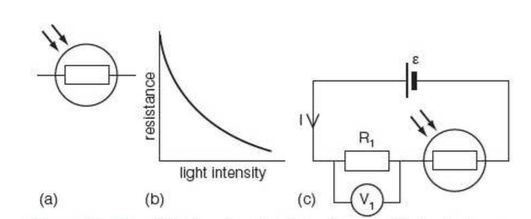
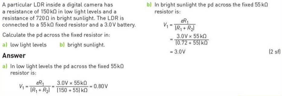
Example
Extra
⇒ Also see our notes on: