Current, Voltage, and Resistance
Current and Voltage
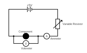
⇒ In this circle, we can look to see how current will vary with changes in voltage for any component
⇒ The ammemeter is always connected in series with the component that is being tested, as to measure the current flowing through it
⇒ The voltemeter is always placed in parallel with the component to measure the total voltage across it
⇒ The voltage supplied by the cell/battery will not change, so you can use a variable resistor to change the current that flows. Then, each time you change the amount of resistance, you can measure the total voltage across the component
Fixed-Value Resistor
⇒ With a fixed-value resistor the resistance cannot be changed
⇒ Thus if we put a fixed-value resistor in place of the 'component', above, and plotted on a graph the voltage and current, there will be a straight line i.e. current is proportional to voltage
⇒ In other words, as the current changes (by changing the variale resistor's resistance), the potential difference (i.e. voltage) changes in proportion.

Filament Lamp
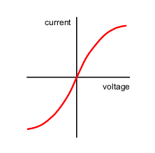
⇒ If we put a filament lamp in place of the 'component', the resistance will increase as current increases (hence the dip in voltage)
⇒ This is because the filament lamp will heat up, which increses resistance
⇒ So, current is not proportional to the voltage in a filament lamp
Resistance Equation
⇒ The current that flows through a component in a circuit will depend on the level of resistance and voltage across the relevant component
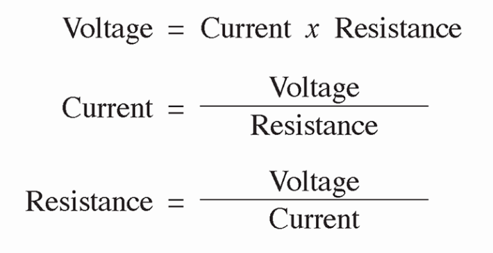
⇒ So you can rearrange the equation to find voltage, resistance or current
Resistance of LDRs and Thermistors
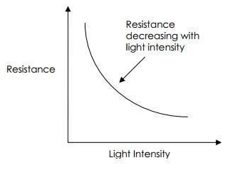
⇒ A light-dependant resistor's (LDR) resistance will depend on the level of light
- It will have the highest resistance when it is completely dark. As the light level increases, the resistance decreases. A LDR is useful for a variety of electronic sensors e.g. automatic night lights
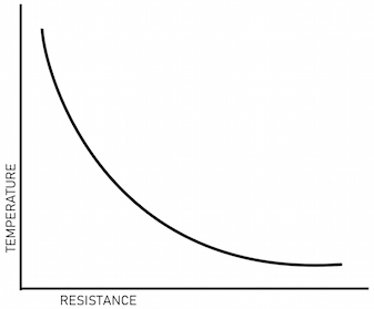
⇒ A thermistor's resistance will vary depending on the temperature
- It will have the highest resistance when it is cold. As the temperature increases, the resistance decreases. A thermistor is useful for a variety of temperature sensors e.g. central-heating thermostats